15921758826
15921758826
Shanghai Weitao automation equipment Co., Ltd
Contact person: Mr. Lu
Tel: 15921758826
Address: 2312 Weiqing East Road, Shanyang Town, Jinshan District, Shanghai
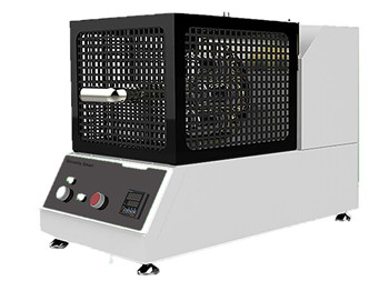
Introduction to xenon lamp aging test box
USES:
Xenon lamp aging test chamber USES xenon arc lamps that can simulate full sunlight spectrum to reproduce destructive light waves in different environments:
1. It can provide corresponding environmental simulation and accelerated tests for scientific research, product development and quality control.
2. Change tests that can be used for the selection of new materials, improvement of existing materials or evaluation of durability after changes in material composition.
3. It can well simulate the changes of materials exposed to sunlight under different environmental conditions.
4. If the test samples are small or few, xenon xenon lamp is recommended to achieve the same effect.
Xenon lamp weather resistance test is an important means to screen formula and optimize product composition in the process of scientific research and production, as well as an important content of product quality inspection. The weather resistance test is required in product standards of applied materials such as coating, plastics, aluminized plastic board and automobile safety glass.
Xenon lamp weathering test box simulation caused by the main factors of material aging is sunlight and moisture, climate testing machine can simulate the damage caused by sunlight, rain and dew.
Xenon lamp weathering chamber using xenon lamp mimic the effects of the sun, rain and dew of condensed moisture simulation, the tested material placed under a certain temperature of light and moisture alternate cycle test in the program, in a few days or weeks time can outdoor months and even years of harm, artificial accelerated aging test data can help to choose new material and improve the existing materials, as well as the evaluation formula of how changes affect the durability of the product.
1. Operational precautions
Lamp installation: Before installing or removing the xenon lamp, the power supply for the safety break switch and the instrument power switch must be turned off.
Cooling cycle: When the test stops, the instrument starts a cooling cycle lasting two minutes to cool the xenon lamp and reduce the humidity of the test chamber.
Do not open the chamber door until the cooling cycle is over.
Hot surface!
During the test, condensation caused hot water to accumulate on the inside of the chamber door.
After the test, please open the door of the test chamber carefully.
Xenon lamp: do not operate xenon combustion tube or glass filter with bare hands.
Skin oil deposits on the skin and burns into the glass.
When holding the lamp, you must wear cotton or rubber gloves.
If the glass has come into contact with the skin, clean it with an optical glass cleaner.
Lamp lead: do not attempt to ignite the lamp when the lead is disconnected, otherwise an arc will form and damage the instrument.
Exhaust system: Do not connect the aging testing machine directly to any existing exhaust system.
Otherwise, the instrument may be damaged due to suction pressure or back pressure, resulting in invalid test.
Oil-water separator: In order to prevent contamination of samples, compressed air can only be supplied to the instrument through the industrial-grade oil-water separator (provided by users).
2. Instrument installation
The instrument installation procedure must be performed by a qualified professional technician.
Unqualified personnel attempting to install may result in serious injury to personnel and damage to equipment.
Prior to installation, consideration must be given to floor space, compressed air, water/drainage and environmental requirements.
3. Facility requirements
Before removing the instrument from the crate, ensure that the facility's air supply and water supply meet the requirements of this section.
Install the instrument in a clean environment conforming to the following specifications.
Environment level and compliance
Temperature range: 16-29℃ (60-85℉)
Humidity range: 0-85%RH, non-condensation
Altitude: up to 2,000 m (6,560 ft)
Storage: 10-43℃ (50-110℉), 20-80%RH
Pollution level: 2
Installation category: 2
(Note: If compliance is greater than installation category 2, the user must provide additional filtering to limit AC input line transients to 2.5kV.)
Safety of laboratory test equipment: EN 61010-1, UL61010-1, CSA61010-1
Mechanical instruction: EN 60204-1
Mechanical safety: ISO 12100-1, ISO 112100-2
Electromagnetic compatibility compliance: EN 61326
4. CE compliance
The laboratory shall be well ventilated to ensure as little airflow, air pollution or dust as possible.
Do not install the instrument in a corrosive or toxic environment or near corrosion testing equipment.
Do not install equipment in warehouses, boiler rooms, garage/factory areas, paint rooms, or places where frequent opening of doors to external environments can cause changes in indoor temperature and humidity.
Such positions may adversely affect instrument operation, longevity, and test integrity (repeatability).
Waste heat and steam generation
By - product waste heat and water vapor are usually produced when the aging machine is in operation.
Most of the waste heat and steam is discharged from the instrument either through the exhaust pipe or through the lamp cooling system heat exchanger.
Residual waste heat and water vapor must be considered when determining the thermal load of the facility's air conditioning system.
A About 50% of the xenon lamp heat is discharged into the air around the instrument through the top pipe.
B Waste heat in the test chamber is also discharged through the exhaust pipe at the top of the instrument.
C Most of the above heat can be captured by the exhaust system of the laboratory, but do not connect the exhaust system of the laboratory directly to the exhaust pipe of the instrument, otherwise it will cause failure and test invalid due to inhalation.
D the heat from the control system and the power transformer/reactor is radiated away through the outer panel of the frame.
E Table 2-1 shows the total heat emitted or radiated into the air around the instrument.
Water requirements
The aging testing machine requires the supply of deionized (DI) water for humidification systems, test specimens, test stand sprayers, and lamp cooling systems.
Cooling lamp Deionized water in the cooling system tank requires standard tap water.
The CS-7 heat exchanger used to transport the tap water is part of a closed loop, so the tap water does not touch the DI water or the sample.
DI water
Pressure: 124-207kPa (18-30psi)
Purity: less than 1ppm of dissolved solids.
Less than 0.1 PPM of silica and rust.
The exhaust pipe
It is recommended that the passenger exhaust pipe be positioned directly above the instrument but not connected to it.
The flow rate must be reduced as much as possible to ensure that the air flow rate of the test chamber does not change when the instrument vent is removed.
2.2 Installation of xenon lamp
Before installing or removing the xenon lamp, be sure to turn off the power supply at the safety break switch and instrument power switch.
Do not turn off the power supply until the lamp has cooled down.
Let the instrument complete the automatic equalization mode for about two minutes.
Do not touch the xenon burner or lamp filter with bare hands.
Skin oil deposits on the skin and burns into the glass.
When holding the lamp, you must wear cotton or rubber gloves.
If the glass has come into contact with the skin, clean it with an optical glass cleaner.
Each aging tester is usually accompanied by a calibrated reference lamp.
Do not disassemble the calibrated reference lamp.
The factory has adjusted the parts.
The calibration lamp provides an accurate irradiance output at the appropriate power level.
The working light is used in normal operation and is equipped with a filter housing to accommodate interchangeable glass filters.
A variety of internal and external filters are available for purchase.
4.png
1.png
Determine the required internal and external filters according to test method before assembling lamps.
Place filters and components on a flat surface that does not slide onto the floor.
Each lamp unit has a pin or hole to determine its location.
Carefully align each pin and matching hole.
This ensures the consistency of the filter each time it is replaced.
The xenon burner must be removed from the lamp before removing other components (filter housing and external filter), otherwise the burner may be damaged.
Place the assembled lamps in the test box.
Position the upper housing of the filter in the nozzle joint of the luminaire.
Twist the lamp until the locating pin is in place, then turn the assembly ring a quarter of a turn clockwise.
Slide the lamp lead clamp to the electrode head, then twist the karmic airfoil screw and tighten the lead clamp.
At this point, the lamp has been installed and is ready to run.
When installing the lead clip, be sure to keep the lead facing away from the burner base to prevent any possibility of arc from the lead.
Install a new gasket in the lamp nozzle joint (seat) to ensure complete sealing when the lamp is turned back and after it is put back.
Heat and lamp installation/removal can degrade gasket performance.
2.png
3.png
Be careful!
Prevent lamp damage
11.png
22.png
33.png
3.0 Widgets and controls
3.1 introduction
This section describes the location and function of aging testing machine parts and controls.
Although each part or control may not be used during normal operation, its exact location needs to be known in a troubleshooting or maintenance program.
3.2 Test box components
(1) Fan: Fan is used to circulate air in the test box.
When the damper is opened, ambient air is drawn in and flows down the intake duct, through the humidifier nozzle, past the air heater, and into the test chamber through the floor vent.
Air flows up through the sample rack and out through an exhaust pipe from the ceiling of the chamber.
When the regulator is closed, the chamber air circulates in a closed loop (without exhaust) to maintain a stable set point temperature.
(2) Relative humidity sensor: This sensor is a solid state capacitive device installed on the top of the test box for monitoring the relative humidity of the test box.
(3) Temperature sensor in the test chamber: also known as "dry bulb" sensor, platinum (PT-100) RTD (resistance temperature detector) is installed in the test chamber.
Used to monitor the temperature of the air in the test chamber.
(4) Exhaust pipe: When the adjusting damper is partially or completely open, the air of the test box will be discharged through this pipe.
The air is usually warm and moist and should be delivered to a facility exhaust system not connected to the physical entity of the exhaust pipe.
(5) Inlet duct: When the regulating damper is partially or completely open, ambient air is inhaled through the inlet air filter and the pipe.
(6) Regulating damper: The "air valve" is automatically controlled to regulate the ventilation between the test box and the surrounding environment.
After a period of minor adjustment, the damper adjusts itself to a fixed position, allowing only a small amount of cold air to be drawn in from the environment.
The air heater is then run to control the test box set point temperature during the current cycle.
(7) Lamp lead: The insulated lead connects the xenon lamp to the igniter.
Since the lead conducts high current at high voltage, it is firmly fixed to the xenon lamp electrode to prevent bad contact and arc formation.
(8) Lamp support/nozzle connector: The xenon lamp is mechanically fixed to the connector, which provides the lamp with an installation position and is capable of connecting the lamp to the supply pipe of the lamp cooling system.
(9) Light rod: The light rod is made of solid quartz and is enclosed in a stainless steel case.
It transmits light from a xenon lamp to a photosensitive sensor.
Xenon lamp: Xenon lamp consists of stainless steel filter upper and lower housing, inner and outer filter, xenon burner.
The spectral output of the xenon burner can be adjusted by using a different combination of internal and external filters.
Select xenon lamp filters for all filters and irradiance ranges.
(11) Sample atomizer: Pressurized deionized water is sprayed onto the front of the sample to simulate the corrosion effect of rainwater and water.
To simulate thermal shock, a cold sample sprayer can be used to spray the sample at a high temperature.
Sample sprayer to use only cold water.
(12) Black panel sensor: The black panel sensor (black panel or black standard) is a platinum (PT-100) resistance-type temperature device installed on the sample clamp.
The black panel temperature is the sum of the chamber temperature and the heat emitted by the infrared (thermal wavelength) part of the xenon lamp spectrum.
Alternatively, a second black panel sensor can be added to the sample mount so that one panel sensor can be used for control and the other for monitoring.
(13) Sample holder Atomizer: Pressurized deionized water is sprayed onto the back of the sample to simulate the dewdrop effect. Due to the rapid cooling effect of the atomizer, warm and humid air in the test chamber condenses on the front of the sample.
Sample stand sprayers are usually started in a dark loop, but can also be modified in a custom program to run in a light loop.
(14) Sample rack: The sample rack is rotated around the xenon lamp at 4rpm to ensure that the sample mounted on the rack receives uniform light.
When the aging testing machine is closed, the sliding clutch enables the sample stand to rotate freely without damaging the transmission system.
Sample clips can be fixed in either combination on the shelf to provide maximum sample size.
(15) Air deflector: The air deflector is a stainless steel ring.
Air flows up through the chamber floor vents and past the air deflector, which directs air to flow over the sample on the test stand.
(16) Air heater: The air heater is a round element that heats ambient air when it flows into the test chamber.
The air heater is responsible for controlling the stable chamber temperature during the test cycle by adjusting the damper in a fixed position.
(17) Test box drain pipe: The gravity drain pipe is used to discharge condensate and water from the test box.
(18) Photosensitive sensor: This photosensitive sensor is used to monitor the irradiance output of xenon lamp.
The enclosure consists of one or two modular capsules, each small container with an interference filter (340nm, 420nm, or 300-400nm) for narrowing the wavelength range of the detected irradiance, and a photodiode for detecting the irradiance.
The light travels down the rod, through an interference filter, and is then projected onto a photodiode, which converts light energy into an electrical signal.
(19) Humidifier nozzle: Humidifier nozzle USES pressurized air and water mixture and stainless steel atomizing nozzle to produce moist fine mist.
The nozzle head has a hanging tip.
The mixture of air and water leaves the nozzle and hits the tip, triggering high-frequency vibrations.
The vibrating tip splits the water molecules even as the water molecules atomize, forming a fog.
Fog is mixed with air intake and enters the chamber through the floor vent.
(20) Relative humidity calibration interface: The interface is inserted into the standard relative humidity sensor for calibration.
(21) Calibration interface of temperature sensor in test chamber: This interface is on time for insertion of RTD standard sensor.
0.png
00.png
000.png
5.0 Determination and handling of functional exceptions:
In case the machine breaks down, please read this manual carefully
Founded in 2011, Shanghai Huitao is a team of experienced engineers and emerging design experts. The company focuses on R & D, design and production of high quality laboratory instruments for textile testing. Headquartered in Shanghai, the company provides high-quality testing instruments and high-quality professional services for companies, academic research institutions and testing institutions of various countries.
Shanghai Huitao continuously launched products to meet the experimental needs of the textile industry. It has advanced microclimate comfort test equipment, such as thermal manikin, thermal and humidity resistance tester, MMT and other test equipment. Meanwhile, it also provides air permeability tester, hydrostatic pressure tester and thermal protective clothing performance test equipment required for new product development. In addition, we have developed and produced many basic textile testing instruments, including washing color fastness tester, fabric abrasion tester, pilling tester, rubbing color fastness tester, ironing fastness tester and perspiration color fastness tester. These high-quality products are widely used in textile testing field. In order to meet the experimental needs of users, we also provide you with innovative and practical testing instruments. The products include fiber tester, yarn tester, fabric tester, carpet tester, geotextile tester and other related testing equipment.
The company sells our products through distributed distribution partners who provide high-quality products, services and support to our customers all over the world. All the products are in line with international quality standards and specifications, and can perform outstanding and accurate product performance.